Earthing is not a one-size-fits-all job. What works in black cotton soil in central India may completely fail in the rocky terrain of Rajasthan or the dry sandy belt of Gujarat. Yet many sites follow generic installation methods and end up with high earth resistance, equipment failures, and safety risks.
This guide covers the installation of earthing for all soil conditions - with practical advice, product choices, and the standards you should follow.
What Is Earthing?
Earthing, also called grounding, is the process of connecting the non-current-carrying parts of an electrical system to the earth. This creates a low-resistance path for fault currents to safely dissipate into the ground.
Without proper earthing, a fault in any electrical equipment can cause electric shock, equipment damage, fire, or even fatalities.
According to IS 3043:2018 (Bureau of Indian Standards - Code of Practice for Earthing), every electrical installation must have a reliable earthing system that meets defined resistance limits. For example:
- Power stations: 0.5 ohms
- EHT substations: 1 ohm
- 33 kV substations: 2 ohms
- Distribution structures: 5 ohms
These are not just numbers - they are safety benchmarks your earthing system must consistently achieve, regardless of the season or soil type.
Why Soil Conditions Affect Earthing Performance?
The earth resistance of any earthing system depends largely on the soil resistivity at the installation site. Soil resistivity is measured in ohm-metres (Ω.m.) and tells you how strongly the soil opposes the flow of electrical current.
Low resistivity = better earthing performance. High resistivity = poor earthing, higher earth resistance.
Several factors affect soil resistivity:
- Moisture content - Wet soils conduct better than dry ones
- Salt and mineral content - Ionic salts improve conductivity
- Soil texture - Clay holds moisture; sand drains fast
- Depth - Deeper layers often have more stable moisture
- Temperature - Frozen soil has very high resistivity
This is why the same electrode installed at two different sites can give completely different resistance readings. The Wenner four-pin method is the standard way to measure soil resistivity before designing any earthing system, as recommended by IS 3043 and IEEE Std 80.
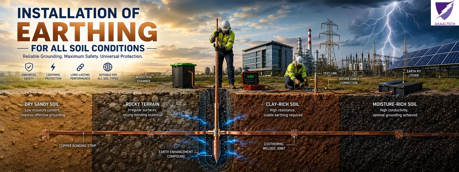
Types of Soil and Their Impact
Rocky Soil
Rocky terrain is one of the most difficult conditions for earthing. The rock itself is a poor conductor, and there is very little moisture to work with.
Driving a conventional GI pipe or copper rod into solid rock is either impossible or ineffective. Earth resistance values in rocky soils can exceed 1,000 Ω.m.
What to do: Use horizontal strip electrodes where surface soil exists, or drill deeper to reach moist sub-strata. Chemical earthing with high-conductivity backfill compounds is often the only reliable option in such conditions.
Sandy Soil
Sandy soil drains water quickly and retains very little moisture. As a result, it has high resistivity - typically between 500 and 1,000 Ω.m. or more in dry seasons.
An electrode installed in sand during monsoon may show acceptable resistance but fail badly in summer. This is a common problem seen at telecom towers, rural substations, and highway infrastructure projects.
What to do: Install chemical earthing electrodes with moisture-retaining backfill compounds such as bentonite. Multiple electrodes in parallel also help reduce overall resistance.
Clay Soil
Clay soil is generally good for earthing. It holds moisture well and has relatively low resistivity - often between 20 and 100 Ω.m. in normal conditions.
However, black cotton soil (a type of expansive clay found widely in Maharashtra, Andhra Pradesh, and Madhya Pradesh) can have resistivity ranging from 300 to 600 Ω.m.. This surprises many engineers who assume clay is always ideal.
What to do: Standard GI pipe or copper plate electrodes often work well in clay. For black cotton soil, conduct proper soil testing and consider chemical earthing for stable long-term performance.
Wet Soil
Marshy or waterlogged areas have naturally low resistivity and excellent conductivity. Earthing in such conditions is generally easier to achieve.
That said, wet environments accelerate corrosion of GI (galvanised iron) electrodes and strips. Over time, corroded connections increase resistance and compromise the system.
What to do: Use copper earthing plates or copper-bonded electrodes in permanently wet or corrosive soils. While the upfront cost is higher, the long service life makes copper the better choice here.
Dry Soil
Arid and semi-arid regions - such as parts of Rajasthan, Gujarat, and the Deccan plateau - have very dry soil with high resistivity during most of the year.
A conventional earth pit may work during the monsoon but go out of specification within a few months. This creates a false sense of safety.
What to do: Install deep electrodes to reach moist sub-layers. Use chemical earthing systems that retain moisture and maintain consistent resistance year-round.
Best Earthing Solutions for Different Soil Conditions
Choosing the right electrode and material is essential. Here is a practical summary:
| Soil Type | Recommended Solution |
|---|---|
| Rocky | Chemical earthing + horizontal strips |
| Sandy | Chemical earthing electrode + bentonite backfill |
| Clay (Normal) | GI pipe/plate or copper plate electrodes |
| Black Cotton Soil | Chemical earthing with soil testing |
| Wet / Marshy | Copper earthing plates, copper-bonded rods |
| Dry / Arid | Deep chemical earthing, multiple electrodes |
GI earthing plates and GI earthing strips are widely used for standard soil conditions. They are cost-effective and easy to install. However, in aggressive or corrosive soils, galvanised earthing strips degrade faster, and copper alternatives are a better long-term investment.
At Akaaltech, we manufacture and supply GI earthing plates, GI earthing strips, galvanized earthing strips, and copper earthing plates - all manufactured to meet IS 3043 specifications, so you get the right product for the right application.
Role of Chemical Earthing
Chemical earthing has become the standard solution for challenging soil conditions across India. Unlike conventional earthing systems that rely on salt and charcoal, chemical earthing uses engineered electrodes packed with advanced backfill compounds.
Here is how it works:
- A specially designed electrode (GI or copper-bonded) is placed vertically in the ground
- The electrode is surrounded by a chemical backfill compound - usually bentonite-based or silica-based
- The compound absorbs and retains moisture from the surrounding soil
- This keeps soil resistivity consistently low throughout the year, regardless of seasonal changes
Chemical earthing electrodes can maintain earth resistance below the permissible limits even in rocky, sandy, or dry soil. That is why telecom companies, power utilities, data centres, and industrial plants across India now prefer this method.
As reliable chemical earthing electrode manufacturers, Akaaltech supplies maintenance-free earthing systems designed for long service life and stable performance.
Installation Process
A proper earthing installation follows these steps:
- Step 1 - Soil Resistivity Test Use the Wenner four-pin method to measure soil resistivity at the site. This determines electrode type, depth, and the number of electrodes required.
- Step 2 - Site Selection Choose a location away from building foundations, drainage pipes, and areas with heavy foot traffic. Shaded, naturally moist areas work better than exposed sunny spots.
- Step 3 - Pit Excavation Dig a pit of 4 to 5 inches diameter, typically 1 to 3 metres deep depending on electrode size and soil conditions. For rocky or dry soil, go deeper.
- Step 4 - Electrode Placement Place the electrode vertically in the pit. For chemical earthing, fill the space around the electrode with the backfill compound in layers, compacting gently.
- Step 5 - Connections and Bonding Connect the earthing conductor (GI strip or copper strip) from the electrode to the equipment earthing terminal. All connections must be tight and corrosion-protected.
- Step 6 - Water Filling (Initial) For chemical earthing, fill the pit with water at installation to activate the backfill compound. The compound swells and binds with surrounding soil.
- Step 7 - Testing Measure earth resistance with a 4-pin earth tester as per IS 3043 Annex A. Record the results. The reading should meet the permissible values for your installation type.
- Step 8 - Documentation Record soil resistivity data, electrode specifications, installation depth, and resistance values. This is required for compliance and future maintenance.
Common Mistakes During Installation
Several avoidable errors lead to underperforming earthing systems:
- Skipping soil resistivity testing - Installing electrodes without measuring soil resistivity is guesswork. Many engineers assume 100 Ω.m. as a default, but actual values can be 3 to 6 times higher at certain sites.
- Too shallow a pit - Shallow installation misses the moist sub-soil layers and gives poor resistance values, especially in dry or rocky conditions.
- Wrong electrode material - Using GI electrodes in highly corrosive or permanently wet soil leads to rapid degradation and rising resistance over time.
- Poor connections - Loose or corroded cable lugs and clamp joints are a major cause of high resistance readings post-installation.
- No repeat testing - Earth resistance changes with seasons. A system that tested fine in July may fail in April. Skipping annual testing is a compliance and safety risk.
- No water provision - Chemical earthing electrodes require periodic water addition in dry seasons. Neglecting this defeats the purpose of the system.
Maintenance Requirements
A well-installed earthing system still needs periodic attention:
- Test earth resistance every 6 to 12 months - Use a 4-pin earth tester and compare results against baseline and IS 3043 permissible values.
- Water the electrode pit - For chemical earthing in dry areas, pour water into the funnel or inspection chamber every few months to maintain soil moisture.
- Inspect all connections - Check electrode terminal clamps, GI strips or copper strips, and conductor joints for corrosion, looseness, or physical damage.
- Check for soil settlement - In sandy or loose soils, the pit may collapse or settle over time, reducing electrode contact.
- Replace deteriorated backfill - If resistance values rise despite adequate moisture, the backfill compound may have lost effectiveness and need replacement.
For installations in industrial facilities, data centres, or substations, maintain a proper earthing log with dates, test values, and corrective actions. This supports both safety audits and regulatory compliance.
FAQs
1. What is the minimum earth resistance required as per IS 3043?
The acceptable earth resistance depends on the installation type. IS 3043:2018 specifies 0.5 ohms for power stations, 1 ohm for EHT substations, 2 ohms for 33 kV substations, and up to 5 ohms for distribution transformer structures. Lower values are always safer.
2. Which is better - GI earthing plates or copper earthing plates?
GI (galvanised iron) plates are cost-effective and suitable for normal soil conditions. Copper earthing plates offer superior corrosion resistance and are preferred in wet, marshy, or chemically aggressive soils where long service life is needed.
3. How deep should an earthing electrode be installed?
Depth depends on soil conditions. In normal soil, 1 to 3 metres is standard. In rocky, sandy, or dry soils, deeper installation is required to reach moist sub-layers. Soil resistivity testing guides the final depth.
4. What is the use of backfill compound in chemical earthing?
Backfill compounds - typically bentonite or silica-based - improve conductivity around the electrode, retain moisture, and lower soil resistivity. This helps maintain stable earth resistance year-round, even in dry or high-resistivity soils.
5. Can I use the same earthing system for lightning protection and equipment earthing?
IS 3043 handles power-frequency fault currents, while IEC 62305 / IS IEC 62305 governs lightning protection systems. A common earth grid can often serve both purposes, but the design must meet requirements of both standards. Always consult a qualified engineer for high-risk installations.
6. How often should I test the earthing system?
Test at least once a year, and preferably every six months. Test at the end of the dry season when resistance is typically at its highest. Keep records of all readings.
7. What is the difference between a GI earthing strip and a galvanised earthing strip?
Both terms refer to the same product - a flat conductor made from galvanised iron (GI) used to connect electrodes to equipment. They are used as horizontal conductors in earth pits and to link multiple electrode pits together.
8. Why does earth resistance increase during summer?
Soil moisture drops in summer, raising soil resistivity. This reduces conductivity around the electrode and pushes up the earth resistance reading. Chemical earthing with moisture-retaining backfill compounds mitigates this seasonal variation significantly.
9. Is chemical earthing suitable for residential buildings?
Yes. Chemical earthing is suitable for residential, commercial, and industrial installations. It is particularly useful in urban areas where soil conditions are unpredictable or where conventional earthing methods do not achieve required resistance values.
10. What standards govern earthing installation in India?
The primary standard is IS 3043:2018 (Bureau of Indian Standards). International references include IEC 60364-5-54 (low-voltage electrical installations) and IEEE Std 80 (substation grounding). Lightning protection earthing is governed by IS/IEC 62305.
Conclusion
The installation of earthing for all soil conditions requires more than just driving a rod into the ground. It demands proper soil testing, the right electrode and material choice, correct installation depth, and periodic maintenance.
Rocky and sandy soils need chemical earthing with quality backfill compounds. Wet soils call for corrosion-resistant copper plates. Clay soils may work with standard GI solutions - but black cotton soil needs careful design. Dry soils need deep installation and moisture management.
Getting this right the first time saves rework, reduces safety risks, and keeps your installation compliant with IS 3043 and related standards.
Akaaltech manufactures a full range of earthing products - GI earthing plates, GI earthing strips, galvanized earthing strips, copper earthing plates, and chemical earthing electrodes - built to meet the demands of every soil condition and installation type.
